A sequence diagram is part of UML - Unified Modeling Language. They visually represent the interactions between objects or components in a system over time. They focus on the order and timing of messages or events exchanged between different system elements. The diagram captures how objects communicate with each other through a series of messages, providing a clear view of the sequence of operations or processes.
Why use it?
Sequence diagrams are used because they offer a clear and detailed visualization of the interactions between objects or components in a system, focusing on the order and timing of these interactions. They provide an intuitive way to convey system behaviour, helping teams understand complex interactions without diving into code. Sequence diagrams are useful for analyzing and representing use cases, making it clear how specific processes are executed within a system.
Notation
1. Actors

An actor represents a type of role where it interacts with the system and its objects. An actor is always outside the scope of the system we aim to model using the UML diagram. We use actors to depict various roles including human users and other external subjects.

2. Lifelines
A lifeline is a named element which depicts an individual participant in a sequence diagram. So basically each instance in a sequence diagram is represented by a lifeline. Lifeline elements are located at the top in a sequence diagram.

3. Messages
Messages are the communication between objects, The messages appear in a sequential order. We use arrows to depict messages.

There are different ways to depict async messages and normal messages.
| Type | Description | Image |
|---|---|---|
| Normal message | We use a solid arrow head to represent a synchronous message. |  |
| Async Message | We use a lined arrow head to represent an asynchronous message. | 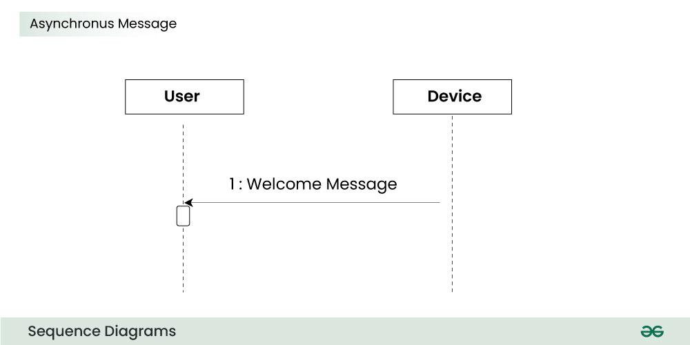 |
4. Create message
We use a Create message to instantiate a new object in the sequence diagram. There are situations when a particular message call requires the creation of an object. It is represented with a dotted arrow and create word labelled on it to specify that it is the create Message symbol.

5. Delete Message
We use a Delete Message to delete an object. When an object is deallocated memory or is destroyed within the system we use the Delete Message symbol. It destroys the occurrence of the object in the system. It is represented by an arrow terminating with a x.

6. Self Message
Certain scenarios might arise where the object needs to send a message to itself. Such messages are called Self Messages and are represented with a U shaped arrow.

7. Reply Message
Reply messages are used to show the message being sent from the receiver to the sender. We represent a return/reply message using an open arrow head with a dotted line. The interaction moves forward only when a reply message is sent by the receiver.

8. Found Message
A Found message is used to represent a scenario where an unknown source sends the message. It is represented using an arrow directed towards a lifeline from an end point.

9. Lost Message
A Lost message is used to represent a scenario where the recipient is not known to the system. It is represented using an arrow directed towards an end point from a lifeline.

10. Guards
To model conditions we use guards in UML. They are used when we need to restrict the flow of messages on the pretext of a condition being met. Guards play an important role in letting software developers know the constraints attached to a system or a particular process.

Sources
Sources