ID: S202605051007
Status: school
Tags: UML - Unified Modeling Language
UML Class Diagram
What are class diagrams?
Class diagrams are a type of UML (Unified Modeling Language) diagram used to visualise or represent the structure and relationships of classes within a system. This is often used to construct and visualize Object Oriented Systems.
Class diagrams can be summarised as boxes with arrows in between with text in those boxes. In theory this makes it so that you can create this in almost any kind of software, but there are a lot of different arrow types which makes it more difficult to do so. I personally use Draw.io.
Quote
Class diagrams provide a high-level overview of a system’s design, helping to communicate and document the structure of the software. They are a fundamental tool in object-oriented design and play a crucial role in the software development lifecycle.
Source: geeksforgeeks
Notations
Class
A class is simple, I can even show you it in obsidian without having to switch to some drawing software. This is because Obsidian supports Mermaid Diagrams.
---
title: Class example
---
classDiagram
    class ClassName
    ClassName : +String publicField
    ClassName : -Bool privateField
    ClassName : +publicMethod(string) string
    ClassName : -privateMethod(int) bool
In the above example we can see a simple example:
- ClassName:
This is the name of the Class or Interface. Whenever it is an Interface, you will put
<<interface>>in front of / above the Classname. - +String publicField: The + or - symbols indicate whether the property / field is public or private. You don’t need to specify whether something is static etc, that will be left for the implementation to decide. Then you put the Datatype of the field, and lastly you put the name of your field.
- +publicMethod(string) string:
The + and - mean the same thing here as it does for the fields. Then you follow with the name of the method, in the above case it is called
publicMethod. Then we follow with all parameters we want to pass into the method, you can decide whether you also want to name them(variablename: string)but I personally don’t since it will look cluttered to me. And then you follow it at the end with the: string, this is the return type of the method.
Access modifiers
The access-modifiers near attributes and methods are defined like this:
| Symbool | Betekenis |
|---|---|
| + | public |
| # | protected |
| ~ | package-private |
| - | private |
Relationships
There are a lot of possible relationship types between classes, I am not going to explain them all, but I will show you the picture that I always use whilst modelling my class diagrams. I advice you to visit geeksforgeeks if you want information on a specific relationship. To use these arrows correctly requires you to know these OOP concepts.
 I created this myself by using the geeks for geeks example.
You will use the Association line (if you think the table is missing the directional association line, look at Association modifiers) for when the relation is not yet defined. You know that it will have a relation, but it is up to the programmer to decide on how to implement it. This is the clear difference between maintaining an class diagram for already existing code and making a diagram for a system you are going to write in the future.
Here is an example image of my class diagram from an old school project. In this example I have used an different version of the Arrows, which is mostly the same, but with a few changes.

Click here to view the picture in full screen, so that you are actually able to read it.
Association modifiers
These are different ways to show an association:
| Symbol | Meaning |
|---|---|
| None, a straight line implies it can be navigated both ways | |
| > | An arrow tells you that class 1 MUST navigate to the other. This |
| X | placing a cross on an end of an arrow disallows the relationship to navigate this way. It is impossible |
So as shown before on the arrow diagram, you can make the association more specific with these 3 above types (which can only be placed on an end of the association line) to be more specific. But it still stays an association.
Multiplicity
Just like an ERD, you are able to specify for each arrow on how many instances there will be. At the classes, the number of instances can be indicated. This notation is placed at the relationships between the classes on the side of the class to which the multiplicity refers.
| Notation | Meaning |
|---|---|
| 1 | There is 1 instance of this class |
| 0..1 | There are 0 or 1 instance of this class |
| 1..5 | There are a minimum of 1 to a maximum of 5 instances of this class |
| 0..* | There are 0 or more instances of this class |
| * | There are 0 or more instances of this class |
| 5..* | There are a minimum of 5 or more instances of this class |
| You can ofc choose any number. |
Packages
A package is a cohesive group of classes. You organize your classes into packages based on the SRP (Single Responsibility Principle). In the label above the symbol, you specify the package name, and in the package symbol you display the classes that are contained in the package.
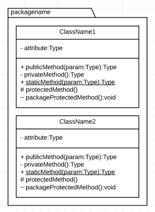
The main package is called the Domainmodel. You create an application within a certain context. Take a library for example, everything related to the library is in the domain (renting, books, copies), but extra classes for logic like printing a receipt is not part of the core functionality, the core idea, and is not in the domain model.
You can create an UML Package Diagram to display all the relationships between packages, this way it is kindof like a C4 Diagram where you can create a class diagram for each package. Or you can just create a big class diagram with all packages, but that will get messy. This is mostly where you will take a different approach based on whether you are documenting already made infrastructure, or designing a new system.
References
Go visit my friend Thomas his article for more info on this subject.